Member Isolation
This window can be accessed from Isolate Member by Location, Isolate Member by Piecemark, Isolate Member by Number, Isolate Group Member by Location, Isolate Group Member by Piecemark
- General Settings
- Tips and Tricks
- Related Tools
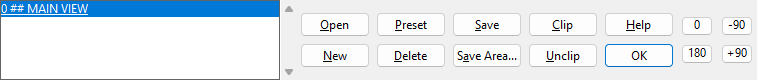
View list : A list of all views that have been added to the member. It lists user-created views after system-created views. The user-created views are numbered per the order in which they are added.
Open : Opens the view selected in the view list . You can double-click a member view name to open that view without having to press the " Open " button.
New : Allows the user to cut a section view transverse to two points that you locate. To add a new view:
1 . Press the " New " button on the Isolate Member toolbox.
2 . Locate- Pan -Return mouse bindings are activated along with various Locate options. Left-click ( Locate ) the points at which you want the section view drawn.
Note: The arrow head that appears as you move the mouse pointer points in the direction you will be looking when you access the view you are creating. Generally you will want the arrow facing toward the material.
3 . The new member view you create appears in your current view as a grid line (a construction line with a number labeled on it). You can double-click on the view number to open the view. In the view list , the new view is the last name listed, and it is named " CROSS SECTION (user created) ." Right-click ( Return ) if you are done adding views.
Preset : Brings up a list of preset views that can be automatically generated for you.
Check the box ( ![]() ) next to the name of the view you wish to add. Preset views are based on the MAIN VIEW for all members but group members. For group members, preset views are based on the " Main member ."
) next to the name of the view you wish to add. Preset views are based on the MAIN VIEW for all members but group members. For group members, preset views are based on the " Main member ."
|
This example shows the preset views that are available for beams. The " BOTTOM FLANGE VIEW " is a "worm's eye view." A related setup option is " Preferred bottom flange view style " in Member Detailing Settings . |
Note : The Duplicate View dialog opens if you attempted to create a preset view of a type that already exists. The dialog informs you of the type of duplicate view that has been detected and gives you three options for saving your new view:
"Replace" replaces the other view of that type that is already on the view list with the new, duplicate view.
"Abort" cancels the adding of the duplicate view.
Delete : Opens a list of member views that you can delete.
1 . Open a view that is not one of the views you want to delete. Press the " Delete " button on the Isolate Member toolbox.
2 . The Select View(s) to Delete window opens. On it is a list of all member views of the member you are currently viewing (with the exception of your current view).
3 . Select the member view(s) you want to delete. Press the " OK " button.
4 . The member views you selected are erased, and you remain in the view that you started in.
Warning: Deleting a member view prevents it from being automatically detailed as a part of 2D detail drawings when you Detail Members . For this reason, you are prevented from deleting main views on all member types.
Note : The main reason to delete a member view is to prevent that view from appearing on a member detail (created when you Detail Members ).
Save : Saves the current view either as a new view or replacing the view that is currently selected. To use save view :
Note: You need to press " Save " in order to retain changes made using " Clip "or " Unclip " or " Depth Checking ."
1 . Press the " Save " button on the Isolate Member toolbox.
2 . The Save Member View window opens. Press one of the following buttons:
"Save" saves the changes made to your current view.
"New View" saves your on-screen perspective as a new view. If the new view is perpendicular to the view it was created from, a prompt opens, " Do you want this view to be a Projected View? " Press the " Yes " button if you want a projected view or press " No " if you want a normal cross section.
"Cancel" ends the save operation and keeps everything as it was before step 1.
3 . The view you started in remains your current view. If you created a view with a new name using this procedure, that view is the last view on the view list and has (user created) written next to it.
Save Area : Allows you to save an erection view that includes your current member plus all adjoining members. See Save Area View.
Clip : Allows you to set detailing clip settings to the view that is currently selected. This sets a boundary that can either include or exclude 2D polygons when the member is detailed. To do a Clip operation:
1 .Press the " Clip " button
2 . Hold down the left mouse button and drag the mouse pointer to form an area box around the section of the member you want to see or cut away in the 2D member detail when you Detail Members.
3 . The Modify View window opens, select one (1) of the following:
Alternative 1 : Press " Inside " to save the area inside the area box.
Alternative 2 : Press " Outside " to save the areas outside the area box.
Alternative 3 : Press " Cancel " to end the Clip operation without changing anything.
Possibility 1 : An X is placed inside the region surrounded by the dashed box if you pressed the " Outside " button. The X marks the area that will not be drawn on this particular view when you Detail Members and select this member's piecemark.
Possibility 2 : A simple dashed box (without an X in it) is shown if you pressed the " Inside " button. The dashed box marks the area that will be drawn on this particular view when you Detail Members and select this member's piecemark.

Unclip : Removes existing detailing clip settings from the view that is currently selected.
- Views on member isolation's view list are applied to the affected detail when you Detail Members . This illustration shows the three views on a detail along with the view list.
- For beams, columns and braces with automatically generated connections, any member views necessary for fabrication purposes are automatically generated without your having to generate special user created views. However, for miscellaneous members, legacy miscellaneous members and group members, creating a preset view before auto detailing may be the best way for you to obtain a good detail of that member.
- When you use Create Group Member , you select the member that you want to be the " Main member ." By default, the box for " Main view locked to main member " is checked, which means that this member is also the MAIN VIEW of the group member.
- In member isolation, you can alter the "MAIN VIEW" of a group member. If you try to " Save " changes made to the MAIN VIEW and the box for " Main view locked to main member " is checked, member isolation opens a yes-no dialog that gives you the option to unlock.
- Depth checking defaults for preset views are set up in Home > Project Settings > Fabricator > Member View Defaults . You can use depth check controls followed by " Save " to override those depth checking defaults for individual preset views.
- System-created views are automatically created during Create Solids . Create Solids automatically generates whatever views are necessary to show dimensioning of materials and holes on the member detail .
- User-created views are created using the " Preset ," " New ," or " Save " buttons. They have the words " user created " in parentheses ( ) next to their name in the view list.
- Any member views added to a member in isolation are automatically added to all members in the 3D model with the same piecemark. These member views appear on the detail for those members (after you Detail Members ).
- Members cannot be brought into isolation until they have undergone Create Solids .
- A projected view can be taken from any view (main, top, end, etc.). While in that view, use View > Section View or View > Snap to Adjacent Surface to create a preliminary snapshot of the projected view. The projected view must be perpendicular to your current view.
-
Auto detailing can rotate the main view of a member for you. You should check to see if these options will work for you before you try to change the view in member isolation. The options are found in Home > Project Settings > Fabricator > Member Detaling/Fabrication Options.
Member Detaling/Fabrication Options Beam " Detailed " (" In position ' or " Horizontal ') Column " Detailed " (" In Position ' or " Horizontal ' or " Vertica l') Vertical Brace " Detailed " (" In position ' or " Horizontal ') Horizontal Brace " Detailed " (" In position ' or " Horizontal ') [Legacy]
Miscellaneous" Detailed " (" In Position " or " Horizontal " or " Vertical ") -
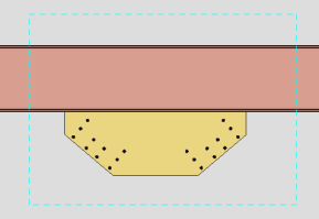
You can change the " In " and " Out " depth of a member view on a case-by-case basis.
The bottom flange cannot be seen because the cope puts it out of the depth In range.
Here the depth " In " range has been increased so that the view can see past the cope to the bottom flange of the beam. -
Examples of preset views :
- Detail Members (draws 3D member views in 2D)
- Detail Member Groups (draws 3D member views in 2D)
- Member View Defaults (Home > Project Settings > Fabricator > )
- Preferred bottom flange view style ( Fabricator > Detailing > Member Detailing Settings > " Beams " tab > )
- Member isolation solid display type ( User and Site Options > Modeling > )
- Depth check controls (can change a view's depth check limits, permanently if followed by " Save ")
- Section View (a way to add views in the Drawing Editor )
- Save View As (can be used in member isolation)
- Material Isolation's edit views mode (for adding views to material)
- Isolate Member by Location
- Isolate Member by Piecemark
- Isolate Member by Number
- Isolate Group Member by Location
- Isolate Group Member by Piecemark

